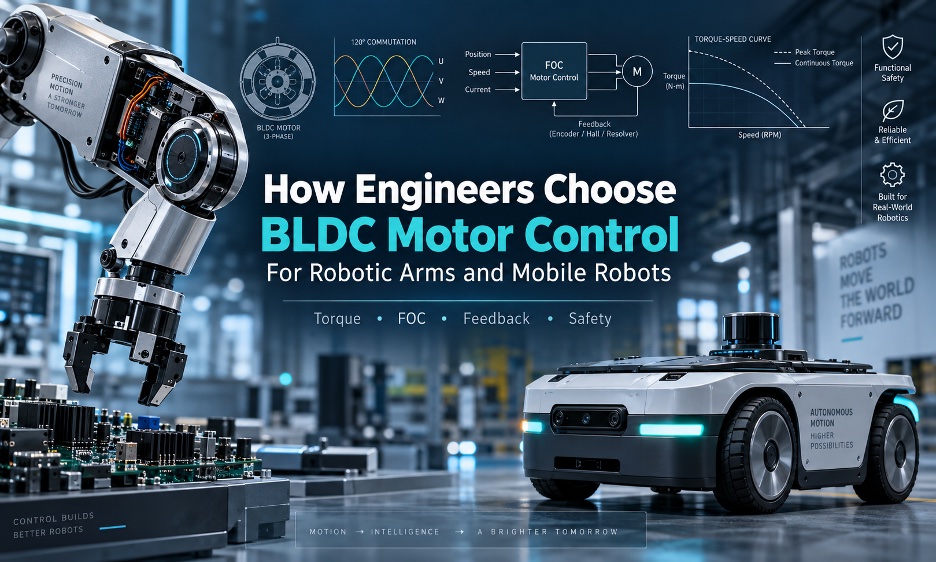
There are several factors to choosing brushless DC or BLDC motors for robots. Source: Faisal Mahmood
Selecting a brushless DC, or BLDC, motor for robotic arms or mobile robots starts with the mechanical system, not the controller catalog. A motor rated for a particular voltage and wattage does not tell an engineer whether it can deliver the required torque at low speed, regulate position accurately, absorb regenerative energy, or survive the thermal duty cycle.
The actuator is a system. The motor, inverter, current sensors, rotor position feedback, gearbox, brake, output encoder, thermal path, communications interface, and higher level robot software all influence the result.
An industrial or collaborative robotic arm joint generally prioritizes controllable torque, low-speed smoothness, position accuracy, collision response, backdrivability, and thermal performance. A mobile robot drive motor generally puts more emphasis on efficiency, starting torque, braking, traction, battery utilization, speed regulation, and synchronization between drive channels.
The terminology also deserves care. Commercial robotics literature often uses “BLDC” and “PMSM” (permanent magnet synchronous motor) somewhat interchangeably because both are three-phase, permanent-magnet machines driven by electronic inverters. Their back EMF waveform, winding design, controller algorithm, and feedback method still determine how a particular motor behaves.
For example, STMicroelectromics treats three-phase BLDC and PMSM control as related application areas and describes both six-step and field-oriented control architectures.
Start with the mechanical load, not the controller catalog
The first selection exercise is to establish what the motor actually has to do. For a geared robotic joint, a useful first order relationship is: τ_joint = (τ_motor × gear ratio × η_gear) − τ_losses
Motor speed follows the transmission ratio: ω_motor = ω_joint × gear ratio
Mechanical power is: P_mech = τ × ω
And a first approximation of battery side electrical power is: P_elec ≈ P_mech / η_total
These equations do not replace a dynamic model, but they expose the parameters that matter before a controller is selected. Considerations include continuous torque, peak torque, peak duration, acceleration torque, gravity torque, and reflected inertia. In addition, regenerative braking, stall or near stall operation, duty cycle, thermal resistance, battery voltage range, and cable and connector current limits should all be established.
For robotic arms, the load calculation has to account for link inertia, payload, gravity compensation, gearbox ratio, backlash, compliance, counterbalance, and encoder location. A motor side encoder can report the rotor position accurately while the joint output still contains transmission error.
For mobile robots, the equivalent exercise starts with vehicle mass, wheel radius, rolling resistance, slope, acceleration, terrain, wheel slip, and drive configuration. Differential-drive platforms impose different synchronization requirements from four wheel drive vehicles. An outdoor uncrewed ground vehicle (UGV) can also spend much more time in high load operation than a lightweight indoor delivery robot.
Regenerative energy deserves particular attention. During deceleration or downhill travel, the motor can return energy to the DC bus. The battery, controller, braking strategy, and bus capacitance all have to accommodate that energy. A controller that handles acceleration correctly can still create an over-voltage problem during aggressive regenerative braking.
 Register now and help us celebrate 20 years of RoboBusiness!
Choose the commutation method according to motion quality
Six-step, sinusoidal, and field-oriented controls are not interchangeable labels for the same behavior.
Six-step, or trapezoidal, commutation switches the inverter through six electrical states according to rotor position. It can be attractive where implementation simplicity and cost matter or torque ripple is acceptable. It can also be suitable when the motor spends much of its operating time at moderate or high speed and precise low speed torque is not a central requirement. Hall sensors can provide the rotor position information needed for straightforward sensored implementations.
Sinusoidal control drives the phases with continuously varying current or voltage references rather than the discrete commutation states associated with basic six-step operation. It can reduce torque ripple and acoustic effects compared with a simple trapezoidal strategy, although actual performance depends on motor construction, feedback, current regulation, and tuning.
Field-oriented control, or FOC, takes the control problem further by transforming the measured phase currents into a rotating reference frame. The Clarke transformation converts the three phase quantities into a stationary two-axis representation, while the Park transformation rotates that representation into d axis and q axis components.
The controller can then regulate the components independently through current loops before transforming the command back into phase voltages and generating pulse width modulation (PWM).
In a typical PMSM application, q axis current is closely associated with torque production, while d axis current can be used for flux related control and, at higher speeds, field weakening. TI‘s motor control reference material illustrates the practical structure with Clarke and Park transformations, PI regulators, position and speed loops, and space vector PWM.
FOC is commonly attractive when the application requires smooth low-speed motion, fast torque response, or accurate speed regulation. It can also help with reduced torque ripple, regenerative braking, field weakening, or torque control for impedance and force-related behavior. FOC can therefore be a natural fit for many robotic joint and traction applications.
FOC does not automatically create a precision actuator. Rotor angle accuracy, current sense quality, motor parameter identification, sampling timing, inverter dead time, loop bandwidth, mechanical transmission, and tuning all affect the final result. A highly sophisticated algorithm cannot compensate for an encoder that is incorrectly aligned or a gearbox with substantial mechanical error.
Select the feedback architecture
Feedback selection is as important as the commutation algorithm. Hall effect sensors, incremental encoders, absolute magnetic encoders, optical encoders, resolvers, and sensorless estimation each solve different problems.
Hall sensors provide relatively coarse rotor position information and are often adequate for electronic commutation and basic speed control. They can be practical for cost-sensitive mobile platforms where the control objective does not require fine position information.
Incremental encoders provide substantially more position information and are widely used for servo control. Absolute encoders add an unambiguous position reference, which can be valuable when a robot has to know joint position immediately after startup without performing a homing sequence.
Optical encoders can provide high resolution but require appropriate mechanical and environmental protection. Magnetic encoders can offer compact packaging and tolerance for some contamination environments. Resolvers remain relevant where electrical and mechanical robustness are important.
The location of the sensor is just as important as its resolution. A motor-side encoder measures motor position. With a reduction gearbox, the output position also depends on gear ratio, backlash, compliance, torsional windup, bearing deformation, and transmission error. If those errors materially affect the task, an output side encoder can close the control loop around the actual joint position.
That does not mean every robot joint requires dual encoders. The mechanical transmission determines whether motor-side feedback provides sufficient accuracy. The Robot Report has previously covered actuator architectures using integrated servo drives and dual absolute encoders, illustrating why encoder placement becomes a system-level design issue as actuator size and performance requirements increase.
Sensorless BLDC control eliminates position sensors and their wiring, reducing cost and packaging complexity. Back EMF-based methods are established engineering techniques, and Microchip documents several implementations. The limitation is that back EMF information becomes difficult to obtain at zero and very low speed, so startup and heavily loaded low-speed operation require an appropriate strategy.
Sensorless control can therefore be useful in applications where the operating profile gives the estimator enough information, but it should not be treated as universally appropriate or inappropriate.
Match the controller to the robotic arm
A simple robotic arm joint can use a BLDC motor with Hall sensors and an external controller when the application mainly requires speed or basic position control and can tolerate relatively coarse rotor feedback. This architecture can be straightforward to commission and service, but the achievable motion quality depends heavily on the motor, gearbox, sensor resolution, controller capabilities, and higher level feedback.
A more demanding robotic joint commonly uses a BLDC or PMSM with an encoder based FOC servo drive. The drive can run a fast current loop locally, with velocity and position loops layered above it. The robot controller then commands the desired operating variable while the servo drive handles the high speed electrical control.
This architecture makes torque control practical and provides a foundation for position, velocity, impedance, and collision response strategies. Commissioning also becomes more involved. Encoder alignment, direction, current sense polarity, current loop tuning, velocity loop tuning, position loop tuning, fault thresholds, and brake timing all become part of the integration task.
An integrated robotic actuator combines some or all of the motor, gearbox, encoder, drive electronics, brake, temperature sensing, and communications interface. The attraction is obvious: fewer separate components, shorter wiring, compact packaging, and a defined interface between the actuator and robot controller.
The engineering tradeoff moves toward heat rejection, serviceability, firmware visibility, replacement strategy, and dependence on the actuator supplier.
The Robot Report‘s coverage of BLDC motors developed specifically for robot joints is one example of how motor packaging and performance requirements are increasingly considered together at the actuator level rather than as isolated motor components.
For any arm, the selection review should cover peak torque at every joint, holding torque at zero speed, brake requirements, backdrivability, and collision detection, torque estimation accuracy, and encoder placement. It should also cover gearbox efficiency, thermal soak, cable routing, mechanical compliance, emergency stop behavior, and safe torque disable or an equivalent safety function.
Match the controller to the mobile robot
BLDC motor control for mobile robots has a different emphasis because the wheels are both propulsion and contact with the environment.
A differential drive autonomous mobile robot (AMR) needs the two drive channels to track commanded velocities accurately enough for stable motion and navigation. Wheel speed feedback also contributes directly to odometry. Higher-resolution encoders become valuable when localization, synchronization, precise docking, or traction control demands more information than Hall commutation signals can provide.
Four-wheeled platforms introduce additional issues. Wheel speed matching, mechanical loading, steering or differential effects, and wheel slip can all influence control. Outdoor UGVs add water, dust, temperature changes, rough terrain, higher inertial loads, and longer periods of sustained power.
Battery behavior also changes the controller decision. Voltage sag under acceleration reduces the available electrical headroom, while regenerative braking can raise DC bus voltage. A controller designed around a nominal battery voltage therefore needs to be evaluated over the complete battery operating range rather than at one nominal value.
Thermal design is another difference. A drive enclosed inside a wheel or compact chassis may have limited airflow. The inverter, motor windings, bearings, connectors, and mechanical structure all become part of the heat path.
Harmonic Drive‘s servo-grade propulsion drive trains for AMRs illustrate this system-level relationship. Their characteristics include smooth travel, backdrivability, torque density, stiffness, and radial load support. The lesson is not that one transmission is appropriate for every AMR, but that propulsion control cannot be separated from the drivetrain.
Mobile manipulators make the distinction even more obvious. Desmasa’s MCR+ combined a robot arm and an AMR that shared one power and control architecture. The drive requirements of the base remained different from those of the arm, even though both ultimately contained electric actuators.
Evaluate current sensing and thermal behavior
Controller current ratings require careful interpretation. A datasheet may list continuous phase current, continuous bus current, peak phase current, peak current duration, RMS current, or a configurable current limit. These numbers are not interchangeable.
The motor’s thermal limit, inverter semiconductor limit, connector rating, cable rating, and battery capability can all be lower than a headline peak current specification. A controller advertised with a large peak current is therefore not automatically suitable for a motor that requires that current continuously.
BLDC.com provides a useful commercial example of the specification categories engineers encounter in controller selection. Its current controller catalog lists different input voltage ranges and current ratings across several controller families, while individual products describe interfaces and protection features.
Those specifications illustrate why engineers should compare voltage range, current definition, duration, feedback compatibility, and protection functions rather than simply comparing wattage.
The heat path must also be considered. Motor winding losses have to leave the motor through its structure and mounting arrangement. Power stage losses must leave the inverter through its enclosure, thermal interface, heat sink, airflow, or mounting structure. Thermal testing under the actual duty cycle is more informative than relying only on a short unloaded bench test.
Consider the communications and software layers
The motor controller is normally responsible for the fastest control loops. A robot controller does not need to calculate every PWM transition. Instead, the drive can execute current regulation and commutation locally while receiving higher level torque, velocity, or position commands.
Before selecting a drive, engineers should check CAN or CANopen support, EtherCAT support, RS 485 or UART, analog and PWM inputs, encoder interfaces, feedback update rates, command latency, fault reporting, firmware update procedures, parameter storage, multi axis synchronization, ROS 2 or ros2_control integration, and CiA 402 support where applicable.
CANopen’s CiA 402 profile standardizes functional behavior for servo drives and other motion control devices, including operating states and command/status structures. That can simplify interoperability when the selected hardware actually implements the required profile.
EtherCAT becomes attractive when synchronized multi axis motion and deterministic timing are central requirements. Its distributed clock architecture allows participating devices to synchronize their local timing.
ROS 2 integration is a separate consideration from the physical bus. Ros2_control represents robot hardware through command and state interfaces and provides a framework for connecting controllers to physical actuators. The controller manager also emphasizes deterministic control loop execution, showing why communication availability alone does not guarantee real time behavior.
Treat safety as an architecture, not a checkbox
A motor controller should be evaluated for overcurrent, short circuit, overvoltage, undervoltage, overtemperature, overspeed, encoder failure, Hall failure, phase loss, stall detection, brake control, communications loss, regenerative voltage rise, unintended restart, emergency stop behavior, and safe torque off where applicable.
These functions are not automatically equivalent to a complete safety architecture. Safety requirements depend on the robot category, risk assessment, operating environment, and system design.
For industrial robots, ISO 10218 1:2025 specifies safety requirements for industrial robots. ISO 13849 1:2023 addresses the design of safety related parts of control systems, including software. IEC 61800 5 2 addresses functional safety considerations for safety related adjustable speed power drive systems.
The important engineering distinction is that a controller having an overcurrent shutdown or temperature sensor does not, by itself, establish a certified safety function. The safety function has to be designed, validated, and integrated according to the applicable requirements.
A practical selection workflow
A useful motor controller selection process can be reduced to ten engineering steps.
- Step 1: Define the complete load and motion profile, including acceleration, deceleration, payload, terrain, gravity, and duty cycle.
- Step 2: Calculate continuous and peak torque at the motor shaft and, where applicable, at the joint or wheel.
- Step 3: Establish the required speed, acceleration, operating range, and regenerative braking conditions.
- Step 4: Define the control objective: speed, torque, position, impedance, or traction.
- Step 5: Select feedback according to the actual control objective and mechanical transmission.
- Step 6: Select six step, sinusoidal, or FOC control based on motion quality, speed range, torque requirements, and implementation constraints.
- Step 7: Check voltage, continuous and peak current, regeneration, thermal margins, and battery behavior.
- Step 8: Select the communication and software interfaces needed by the robot architecture.
- Step 9: Define safety behavior, fault response, braking, communication loss behavior, and restart conditions.
- Step 10: Validate the complete motor, drive, gearbox, sensor, brake, and robot controller as one system.
BLDC motor control selection decision table
| Application requirement | Preferred control direction | Main reason | Important limitation |
| Simple wheel speed control | Sensored six step or simple closed loop control | Low implementation complexity | Coarser torque and position behavior |
| High-efficiency mobile traction | FOC with appropriate feedback | Good torque and speed regulation across a wide operating range | Higher software and tuning complexity |
| Low-speed robotic joint motion | Encoder based FOC | Smooth torque production and precise rotor angle information | Transmission and tuning still limit performance |
| High precision joint positioning | Servo drive with encoder feedback, potentially output feedback | Position loop can account for joint behavior | More sensors, wiring, and integration effort |
| Torque controlled collaborative joint | FOC servo architecture with suitable torque feedback or estimation | Fast current/torque response | Safety and torque accuracy require system validation |
| Sensorless high speed drive | Sensorless commutation or sensorless FOC | Eliminates position sensors and wiring | Startup and very low speed behavior require careful design |
| Multi axis synchronized arm | Networked servo drives, often with deterministic Ethernet | Coordinated timing and distributed control | Network and drive configuration become part of commissioning |
| Harsh outdoor mobile robot | Closed loop drive with feedback selected for the environment | Better speed control, diagnostics, and traction management | Environmental sealing and thermal design remain system level issues |
Commissioning and validation
A controller should not move directly from a wiring diagram to production operation. First, verify phase order and encoder direction. Confirm Hall or encoder alignment and current sense polarity. Run the motor unloaded at reduced voltage where the hardware permits it, then compare commanded and measured speed.
Next, check position error and current behavior. Apply a controlled mechanical load and measure phase current and bus current. Monitor motor and inverter temperatures during acceleration, steady operation, and repeated cycles.
Regenerative braking deserves a dedicated test. Measure the DC bus during controlled deceleration and confirm that the battery, braking circuit, and controller remain within their operating limits.
Communication loss testing should verify what the drive actually does when commands stop arriving. Sensor disconnection tests should confirm fault detection and the resulting state. Overcurrent, thermal protection, emergency stop, and brake behavior should also be tested under controlled conditions.
Finally, repeat the important tests after thermal soak. A drive that behaves correctly for several minutes at room temperature may behave differently after the motor and inverter reach their operating temperatures.
For a robotic arm, these tests should be performed with the gearbox and representative mechanism installed. For a mobile robot, they should include the actual wheel, vehicle mass, battery, terrain, and representative duty cycle. A bench test of an unloaded motor validates only part of the system.
Engineer’s checklist
- What are the continuous and peak torque requirements?
- What is the required speed and acceleration range?
- Is the objective speed, torque, position, impedance, or traction control?
- Is Hall feedback sufficient, or is encoder feedback required?
- Is motor side feedback sufficient for the mechanical transmission?
- Does six step control provide adequate motion quality, or is FOC justified?
- Are voltage, current, regeneration, and thermal margins adequate?
- Does the communications interface meet latency and synchronization requirements?
- What happens during sensor failure, communication loss, braking, and emergency stop?
- Has the complete actuator been tested under the actual mechanical duty cycle?
Pulling together criteria to pick the right motor
The correct BLDC motor control architecture is determined by the control variable, mechanical transmission, feedback quality, duty cycle, thermal limits, energy system, safety architecture, and software integration.
For a simple mobile drive, a sensored six-step controller may provide an adequate combination of cost, robustness, and speed regulation. A demanding robotic joint may instead require encoder based FOC, nested torque, velocity, and position loops, and possibly output side feedback.
An outdoor mobile platform may need closed loop traction control, careful regenerative energy management, environmental protection, and thermal capacity that would be unnecessary on a small indoor robot.
The key decision is therefore not simply which BLDC motor controller has the right voltage or wattage rating. The useful question is whether the complete motor, inverter, feedback system, transmission, power source, communications layer, and safety architecture can produce the required behavior throughout the robot’s actual operating envelope.

About the author
Faisal Mahmood is a seasoned digital marketing and tech content strategist with extensive experience in AI, software development, and SEO-driven content. He specializes in creating deeply researched, fact-based articles that help developers, enterprises, and tech teams understand the latest trends in AI-powered tools, coding best practices, and secure software development.
Mahmood is passionate about bridging the gap between emerging technology and practical insights for global audiences. He is reachable at [email protected].

Tell Us What You Think!