Here’s what happened in a multi-year collaboration among engineers and scientists at New Scale Technologies, austriamicrosystems and TDK-EPC to simultaneously develop the motor, mechanics, electronics and control systems for the M3 piezoelectric micro motor.

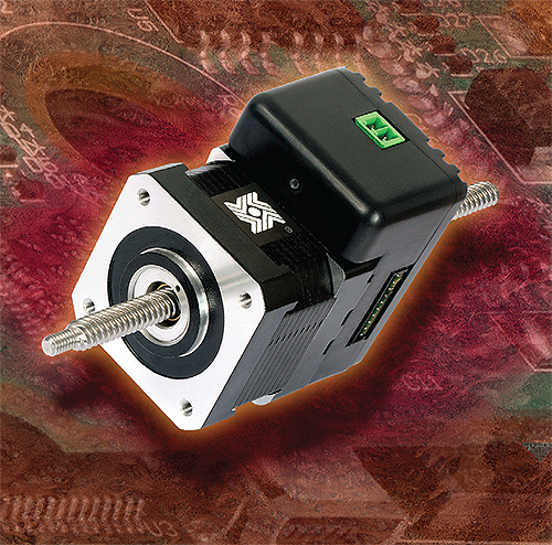
Larger-scale mechatronic systems include this integrated size 17 stepper motor and IDEA drive from Haydon Kerk.
Piezoelectric micro motors satisfy the need for linear motion in miniature products. These millimeter-scale motors are less than half the size of solenoids or traditional electromagnetic micro motors. They are more efficient at small sizes, and produce direct linear motion without gears or drive trains. They also offer longer travel, higher precision and higher force than solenoids or shape memory alloys (SMAs). These features make them suitable for use in portable battery-powered devices, such as miniature focus systems for cameras in phones or industrial laptops, or any application requiring small size and high precision. These include machine vision, optical fiber and RF tuning devices, medical devices, and military systems for vision, targeting and control.

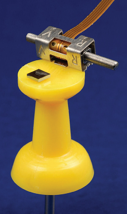
Since 2006, SQUIGGLE piezo motor systems have shrunk in size from (at right) a 12 mm diameter motor with 51 x 76 x 14 mm drive card, to (at left) a 2 x 2 x 5 mm motor with a flip-chip drive ASIC (shown on the dime). This enabled the creation of integrated micro-mechatronics modules such as the M3-L module (center) – complete closed-loop motion systems in housings of less than 7 x 12 x 30 mm.
Designing with piezoelectric (piezo) motors requires a different mindset than that used with traditional servo or stepmotors. The traditional approach of specifying the motor and then buying or designing the control system works for servo and stepmotors because there is a vast body of “cookbook motor” control solutions and experienced drive teams available for traditional motor implementation. This is not the case for piezo motors, which require special drive circuits to create and maintain ultrasonic resonant vibrations in the motor.
In addition, piezo motors are most effective when the mechanics, electronics, control system, software – and even the motor design itself – are developed in concert. In this way the piezoelectric ceramics, the silicon, and the system can be tuned to work together for optimal performance. It is a perfect illustration of the benefits of a mechatronic design process.
Miniaturization meets mechatronics
The last five years have seen impressive miniaturization of piezo motors. One example is our SQUIGGLE motor. Recent innovations have yielded dramatic reductions in the size of the drive electronics. Such reductions were possible in part through collaboration with TDK-EPC to develop new, lower-voltage piezo actuators and eliminate the need for voltage boost circuits; and in part by work with analog IC experts at austriamicrosystems to incorporate more intelligence into the piezo drive ASIC.
These advances enabled new integrated micro-mechatronic modules: small closed-loop actuators that serve as simple “drop in” subsystems in OEM product designs. The system designer provides high-level commands to the module through a standard serial interface. A 3.3 Vdc battery provides power. The mechanical coupling is customized to the application: to move a lens, adjust a grating, push a valve, and so on.
Such micro-mechatronic modules typically provide as much as 50 grams force with precision of one-half micron and closed-loop accuracy measured in tens of microns.
Mechatronics compared to micro-mechatronics
In some ways these micro-mechatronic modules are analogous to larger versions. However, there are important differences. For example, Haydon Kerk combines its IDEA drive with a size 17 stepper motor to create an integrated 60 x 40 x 70 mm mechatronic system that is PC-programmable. According to Haydon Kerk’s Ray LaChance, this integrated drive system is for designers who need a few thousand units per year. Design teams making higher-volume products typically create their own drivers, relying on experienced in-house drive teams and libraries of standard drive approaches.
In contrast, driving piezo motors requires specialized knowledge and experience to create control systems that optimize the motor and drive performance under a range of conditions (including varying input voltage, duty cycle, environment, and load). Load coupling techniques are also important for maximum performance and operating life.

The latest drive ASIC for the SQUIGGLE motor incorporates numerous drive functions that in earlier versions were implemented off-chip. The result is a reduction in overall system size.
Innovation miniaturizes components
Our initial focus was to reduce the size of the motor. The SQUIGGLE motor design has proven to be highly scalable, shrinking by a factor of 100 since the first model was introduced in 2004. The current model measures less than 3 x 3 x 6 mm with housing.
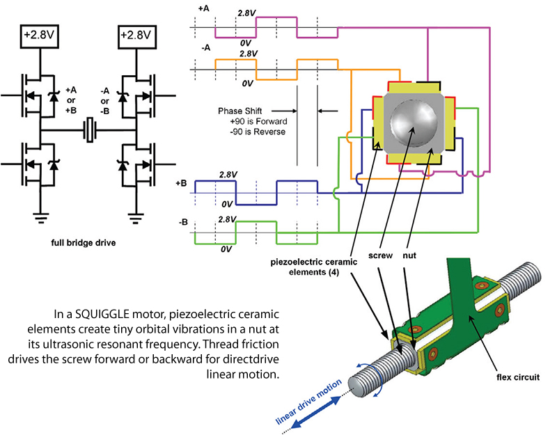
Unlike other piezo motors, where the piezo elements push directly on a stator, this design uses ultrasonic vibrations of the piezo elements to create resonant orbital vibrations in a nut. These minute vibrations drive a threaded screw forward or backward, creating direct-drive linear motion. In this design the piezo ceramics are decoupled from the load path, enabling high force and robustness.
The innovations that allowed miniaturization of this motor included the ability to machine tiny screws with precision threads, greater material choices, fine-tuning the geometry of the piezo ceramics, and creating micro-manufacturing processes for semi-automated and automated assembly of the tiny components.
Next the company turned its focus to miniaturizing the drive electronics. The input to the piezoelectric elements is a set of phase-shifted waveforms that match the resonant frequency of the motor. While other techniques are used, motor speed is typically controlled by varying the amplitude of the voltage.
In the push to miniaturize the drivers, the team zeroed in on the need to reduce the voltage level required to excite the piezoelectric elements. Like most piezo motors, SQUIGGLE motors employ “hard” PZT ceramic material to minimize dielectric losses and associated temperature rise. This material requires an applied voltage of around 40 V to create motion. For battery-power operation, this necessitated a dc-to-dc step-up converter in the drive ASIC, as well as external components to regulate and boost voltage. While total drive footprint for these components was approximately 6 x 9 mm, many OEMs wanted even smaller drivers. Some, especially in medical applications, were uncomfortable with the presence of 40 V in the system even though the drive IC operated on 3.3 V battery power.
In 2008, we partnered with TDK-EPC to develop a piezoelectric drive element with reduced input voltage requirements. The resulting element consists of multiple thin layers of hard piezo ceramic material, co-fired into a single plate. It has the same dimensions and performance as the original monolithic element, but requires only 2.8 V applied voltage.
This change eliminated the need for the step-up converter and boost circuits, and allowed austriamicrosystems to create a smaller driver for the reduced-voltage motor. With this iteration, austriamicrosystems also moved from QFN packaging to wafer-level chip scale packaging (WLCSP), shrinking the drive ASIC from 4 x 4 mm to 1.8 x 1.8 mm. Only two external capacitors are needed, for a total drive circuit footprint of 2 x 3 mm.
At the same time, the design teams packed more features into the smaller chip to enhance motor and system performance. For example, on-chip frequency generation eliminated the need for an external clock. Hybrid full-bridge/half-bridge drivers replaced half-bridge versions, allowing the driver to regulate the voltage to the motor and automatically switch drivers to conserve power at slower speeds, or deliver constant speed as the battery voltage drops. These features reduced system power consumption by more than 30%, providing an additional benefit for battery-operated applications.
Other features in the new ASIC include patent-pending technology to monitor motor performance and adjust the drive frequency to maintain a lock on the mechanical resonant frequency of the motor, which can vary with temperature. This ensures optimal motor performance over wide temperature ranges and high duty cycles.

Miniaturization enables micro-mechatronics
With the drive electronics now smaller than the motor itself, the design team created closed-loop control systems using these components.
SQUIGGLE motors have good position resolution: pulsing the drive signal can cause the motor to move distances as small as half a micrometer per pulse. However, the motor speed—and hence distance travelled per pulse—will vary with applied load and device friction. A closed-loop control system is needed to achieve exact positioning, repeatable bi-directional positioning, or precise speed.
The ability to integrate closed-loop controls into a micro module was aided by recent advances in non-contact position sensors and microprocessors.
The TRACKER position sensor, a joint development by New Scale and austriamicrosystems, is a non-contact magnetic encoder that gives direct digital output, eliminating the need for external pulse counters. At only 3 mm total height including the magnet, it is smaller than optical encoders with glass slides and does not require a light source, which is of particular benefit in optical lens positioning applications. The sensor has a built-in zero reference and 0.5 μm resolution.
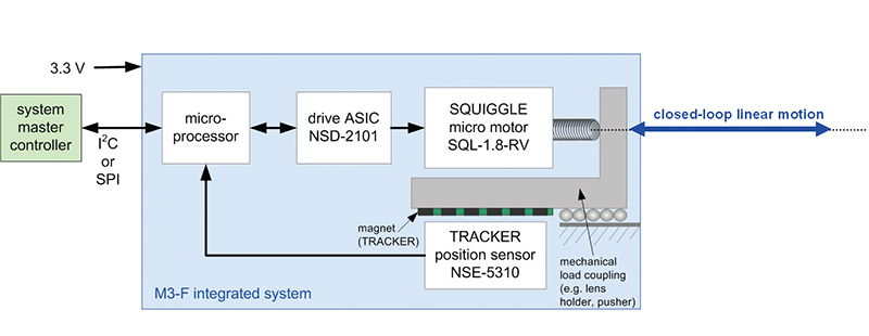
A 2.4 x 2.4 mm mini microprocessor integrates into a module with the motor, driver and position sensor. The microprocessor is small and inexpensive enough to allow the company to add intelligence to the module with negligible impact on cost or size. The microprocessor receives position information from the position sensor, and uses on-board PID control to adjust the motor drive signal based on proximity to the target position.
Embedded in a system, the module accepts high-level ASCII commands from the system controller through standard serial interface (I2C or SPI). The command set includes commands to set the motor speed, move, halt, move a specified distance, and move to a target position.
Thus the module could be used in a number of motion tasks. The move-to-target-position command allows the module to travel to any number of pre-set positions, for example moving a grating to tune a laser to selected wavelengths. The move and halt commands can be used to move the actuator until a given condition is reached, for example in an auto focus system. Camera module developers use their auto focus algorithms to command the actuator to move a lens in either direction and halt when focus is achieved.

Motor, driver, position sensor and microprocessor are integrated to provide closedloop linear motion with simple high-level command input via standard serial interface
The ability to use high-level ASCII commands to move the actuator dramatically simplifies the task of embedding precise micro motion into a system design. For evaluation and testing, a USB adapter lets users connect the module to a PC and end commands to the module using the graphical user interface of New Scale Pathway software.
The M3 micro-motion modules demonstrate the advantage of using the mechatronic design process. Today engineers are using this tiny system-level actuator to add motorized focus to compact biometric sensing and machine vision cameras and create compact RF and optical tuning systems.
New Scale Technologies
www.newscaletech.com
austriamicrosystems
www.austriamicrosystems.com
Haydon Kerk
www.haydonkerk.com
TDK-EPC
www.tdk-epc.us


Tell Us What You Think!